Throughout his illustrious career, Rupert Neve continued to refine the diode‑bridge compressor design he first created over half a century ago.
Few admirers of the late, great Rupert Neve can be unaware of the original Neve 2254 diode‑bridge compressor, introduced in 1969. It became a standard module in Neve’s 80‑series consoles, quickly gaining a reputation for its ability to glue mixes together nicely and also to add punch and colour to individual sources. The core design was also employed in later consoles and standalone dynamics products. Homages and variants of this ingenious design have appeared ever since, some staying faithful to the original circuitry (and its inherent compromises), and others featuring redesigned elements to improve the technical performance. AMS Neve, for example, issued a 2254 recreation which we reviewed back in August 2009.
So it’s not surprising that, 50 years on, Rupert Neve Designs have introduced an updated diode‑bridge compressor of their own. Initially, this appeared as the dynamics section of the Shelford Channel outboard unit but it was subsequently re‑engineered in the form of a 500‑series module, the 535, which we reviewed in SOS May 2018. More recently, this same modernised diode‑bridge compressor design has been reborn as a standalone, dual‑channel, rackmounting version. Called the 5254, it sits within the company’s Shelford range.
Design & Construction
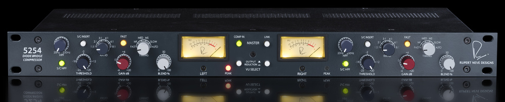
The 5254 has a nicely understated aesthetic, with the familiar dark blue/grey paintwork and elegantly slim colour‑coded control knobs, along with a pair of rectangular VU meters in the centre of the panel, each printed with Rupert’s initial. It looks like a serious, classy, no‑nonsense professional device. I haven’t figured out the logic of the control knobs’ colour‑coding, but there are only six per channel, all with clear and familiar legends and markings. Three are blue/grey (HPF, Threshold and Ratio), two are silver/grey (Timing and Blend) and one is red (Gain).
The Ratio and Timing controls are quite ‘heavy’ rotary switches, although I think they feel stiff only because the knob diameter is so small. Ratio provides rates of 1.5, 2, 3, 4, 6, or 8:1, while the side‑chain’s attack and release time‑constants are controlled together with six pre‑defined ‘Timing’ combinations, identified only as Fast, MF, Medium, MS, Slow and Auto. A Fast button reduces both the attack and release values of each setting by around 30 percent, giving the 5254 a significantly faster reaction time than the original design. The selected time constants also vary slightly depending on the ratio and threshold settings, as well as the dynamic nature of the source material itself — this is an effect that contributes to the unique character of the diode‑bridge compressor.
As an overview of all the options, the attack times range between 0.25 and 80 ms, while the release (recovery) times span 0.1 to 2 seconds, and the longest release times follow a non‑linear curve, which gives a very smooth removal of gain reduction.
The 5254’s auto‑recovery system is a conventional two‑stage release, responding to loud transients with a fast release time of 400‑900 ms, switching to a slower 1‑2 second release curve as the gain reduction diminishes. This arrangement maintains the impression of loudness for transients, while minimising background pumping side‑effects.
The Threshold knob has a continuous detented action spanning ‑25 to +20 dBu and this wide range allows both (pseudo) peak‑limiting at 8:1 for loud signals, as well as extremely gentle glue compression at 1.5:1 for low‑level signals, and everything in between. The variable High‑Pass Filter control is also detented and covers 20 to 250 Hz with a 12dB/octave slope. It’s interesting to note that although the 535 module, with its limited panel real‑estate, made do with a fixed 150Hz side‑chain filter, the original Shelford Channel unit allowed the preamp’s variable high‑pass filter element to be reallocated to the compressor’s side‑chain — it’s nice to see that option included here.
Two more buttons associated with the side‑chain are used to activate the variable high‑pass filter and to enable a rear‑panel insert point. The latter is provided with separate quarter‑inch send and return sockets, an arrangement which usually signifies a balanced I/O so I was surprised to discover that these connections are unbalanced. The inserts also operate at a slightly depressed signal level (nominally 0dBu for a +4dBu input). Naturally, the Send signal is normalled through the Return socket, so the signal path is maintained if the insert button is pressed accidentally with nothing plugged in.
Increased headroom ... means that it could, for example, handle hot levels from pro D‑A converters.
The make‑up Gain control spans a range of ‑6 to +20 dBu, while the Blend feature offers the usual 0 to 100 percent dry/wet mix to create parallel‑compression effects. Again, both knobs have continuous detented actions.
I’m not really a fan of detented controls, as they aren’t as precise as the expensive switches they attempt to emulate and prevent precise alignment. This is most pertinent in the case of the Gain control, with which I could trim the output level to +3.6 or +4.6 dBu but not the +4.0dBu calibration I sought! It’s not a deal‑breaker by any means and the two channels seem well matched, but a minor source of frustration nonetheless.
VU meters, independently switchable to show each channel’s output level (0VU = +4dBu) or amount of gain reduction, are provided for each channel. Two more buttons activate linking between the two channels (to stabilise the image when processing stereo signals) and engage/bypass both compressor channels simultaneously. If desired, an individual channel can be bypassed by turning the blend control to zero percent, of course, and when bypassed (using either technique) the input and output buffers and transformers remain in circuit, so the unit won’t pass audio in the event of power failure.
 insert send and return jack sockets.") On the rear panel, sitting between the main analogue I/O channels, are separate (unbalanced) insert send and return jack sockets.
On the rear panel, sitting between the main analogue I/O channels, are separate (unbalanced) insert send and return jack sockets.
There’s no mains power switch on the front, which is a pet peeve of mine. Instead, it’s tucked around the back, integrated with the universal IEC mains inlet (100‑240 V AC). Sensibly, the line inputs use combi‑XLRs, so balanced line‑level input signals can be hooked up with TRS or XLR connectors. Oddly, though, the outs are only on male XLRs. A slide switch on the rear panel disconnects pin 1 of both output XLRs from the chassis, with the aim of preventing ground loops. As most commercial cables have pin 1 tied to the shell this switch may be completely circumvented. This potential ‘gotcha’ affects the ground‑lift function of many manufacturers’ devices, not just this one, but it’s worthwhile checking your XLR cables to see how they’re wired!
Workings
The 5254 isn’t designed to be perfectly transparent. Like its forebears, it’s meant to impart a distinctly punchy character, and higher signal levels, stronger ratios and faster attack/release settings all produce noticeably more harmonic coloration. Conversely, lower signal levels, gentler ratios, and slower timing options all help to make the compressor sound much more transparent, as does dialling in some dry signal for parallel compression, of course.
 input and (large open‑frame) output transformers are visible, and it appears to use ±24V power rails from the SMPS power supply boards on the right‑hand side, which then seem to be regulated down to ±21V (presumably for the discrete transistor stages) and ±15V, probably for the op‑amp stages.") Removing the lid reveals a well‑made product with good attention to detail throughout. The (small metal) input and (large open‑frame) output transformers are visible, and it appears to use ±24V power rails from the SMPS power supply boards on the right‑hand side, which then seem to be regulated down to ±21V (presumably for the discrete transistor stages) and ±15V, probably for the op‑amp stages.
Removing the lid reveals a well‑made product with good attention to detail throughout. The (small metal) input and (large open‑frame) output transformers are visible, and it appears to use ±24V power rails from the SMPS power supply boards on the right‑hand side, which then seem to be regulated down to ±21V (presumably for the discrete transistor stages) and ±15V, probably for the op‑amp stages.
In the original design, the input signal passed through a transformer and a balanced pad to feed the diode‑bridge directly, with a high‑gain stage recovering the signal and driving the output transformer. Rupert Neve Designs have redeveloped the circuitry quite substantially from that, to provide greater versatility in terms of ratio and timing options, more accurate dynamic control by reacting to both sides of the input waveform, and a substantially lower noise floor. There’s also increased headroom, thanks in part to higher power‑rail voltages, which means that the 5254 could, for example, handle hot levels from pro D‑A converters.
 that reveals the different ratio options. The soft‑knee characteristic is clearly evident, as is a minor level offset in bypass mode.") A set of transfer curves (input level on the horizontal axis, output level on the vertical) that reveals the different ratio options. The soft‑knee characteristic is clearly evident, as is a minor level offset in bypass mode.
A set of transfer curves (input level on the horizontal axis, output level on the vertical) that reveals the different ratio options. The soft‑knee characteristic is clearly evident, as is a minor level offset in bypass mode.
The 5254 design’s custom input transformer unbalances the signal for a solid‑state buffer, the output of which drives either the compressor circuitry or sends the bypass signal straight to the output stage. The compressor circuitry starts with a pair of buffer amplifiers which regenerate a symmetrical signal to feed the diode‑bridge through a balanced attenuator. The output of the bridge feeds a pair of high‑gain amps to recover most of the lost signal level, and their outputs pass to a differential stage which creates an unbalanced signal again, for the rest of the signal path. Next comes the make‑up Gain amplifier, the output of which is combined with the dry input signal using the Blend control to feed a mix amp, with the result being passed to the output amplifier, meter and custom output transformer.
The side‑chain signal is derived from the output of the differential stage (it has a feedback configuration), passing through another amplifier which drives the unbalanced insert send. The insert return passes through its own buffer amp and then feeds the high‑pass filter. The signal then enters the side‑chain processing circuitry to generate a control voltage for the diode‑bridge. The detailed design of the side‑chain processing obviously plays a big role in the sound character of the compressor, and RND have developed the circuitry considerably beyond that in the original design, including using full‑wave rectification to ensure both positive and negative peaks of the input signal are taken into account. The side‑chain’s control voltage can be cross‑coupled with that of the other channel by the Link switch: whichever side generates the strongest control signal ‘wins’!
 This plot compares the levels of the first 10 distortion harmonics when applying 7dB of gain reduction, with a clear dominance of odd harmonics, lead by the third. At both higher and lower levels of gain reduction the amount of harmonic distortion is less.
In Use
Technically, the 5254 performed very well indeed. The only minor niggle was that inability to align output levels precisely due to the detented Gain pots but, while that may frustrate when bench testing, it’s not likely to be a significant problem in normal use. My tests with an Audio Precision test set confirmed that the unit can handle slightly more than +26dBu in and out without difficulty, the frequency response is essentially flat to well beyond 80kHz, and the signal‑noise ratio measured ‑108.7dB (ref +4dBu) with no gain reduction, falling to about ‑84dB with 6dB of active gain reduction. Increasing the make‑up gain also increased the noise floor, of course. The THD measured 0.0008 percent with no gain reduction, rising to a maximum of around 0.3 percent at 6dB of gain reduction. Although both odd and even harmonics were present, the tendency was for a noticeable increase in the third harmonic.
With slow and gentle settings, I found the 5254 sounded pleasantly clean — certainly cleaner than I remember the original 2254 being — but there is still a subtle hint of harmonic richness and character there, and it develops quite obviously with stiffer ratios, faster timings and higher signal levels. This all makes it a little more versatile than the original 2254 and it will undoubtedly have applications on a range of sources, as well as for group and master bus compression.
 An FFT spectrum plot showing effectively the same thing, which compares to...
 harmonic present.") And the same plot but with zero gain reduction for comparison, revealing around 25dB less harmonic distortion, but still with clear third (and some second) harmonic present.
And the same plot but with zero gain reduction for comparison, revealing around 25dB less harmonic distortion, but still with clear third (and some second) harmonic present.
The fast Timings options work well in controlling fast transient sources, like drums and pianos, quite firmly, while gentler settings work very nicely in a mix‑bus application. I thought I’d miss the ability to adjust the attack and release times independently, but in fact the combination settings seemed very well chosen and I had no complaints. On solo instruments and vocals the harmonic character adds a subtle richness and brightness to the sound and really does help those sources to move forward in a busy mix with a subtle but very effective presence.
I described RND’s technologically very similar 535 module as “a bit of a ‘Marmite product’” and I think the same applies here. There are undoubtedly cleaner‑sounding compressors out there for those jobs that require ultimate transparency, but where a little bit of edge and presence suits the project, the 5254 does a really good job, and I like it a great deal.
What Is A Diode Bridge Compressor?
The heart of every compressor or limiter is the gain reduction element — the part that actually attenuates the signal level by an amount determined by the side‑chain control signal — and many different technologies are used in this role, all with different characters and qualities. For example, the opto‑cell uses a light‑dependent resistor and was one of the earliest solutions, along with the vari‑mu concept which attenuates the signal through a valve circuit. Later designs used the fast‑responding solid‑state Field‑Effect Transistor (FET) instead, and then complex VCA‑based systems were introduced with the benefit of much lower distortion artefacts and greater accuracy. There are even systems that use an analogue sampling technique called PWM (pulse width modulation) which, arguably, offers the fastest and most transparent compression of all.
Another, relatively little‑used, technology is the diode‑bridge (or ‘diode‑ring’) which was first introduced in the 1940s in the form of the Telefunken U13. This employed a valve rectifier as the attenuating element, and it was popular with broadcasters at the time because its very fast response time made it invaluable as a peak‑limiter in broadcast transmitter chains. The diode‑bridge design subsequently had a resurgence in popularity in the 1960s when Neve re‑introduced it, as it provided a much faster response than typical opto‑compressors, and rather less distortion than many of the early FET designs too.
A diode is normally used as a simple ‘one‑way valve’ in electronic circuits, allowing current to flow in one direction only. However, there is a small region of its ‘transfer curve’ where its conductance direction varies in proportion to the voltage applied across it, and it’s that characteristic that allows its use as an adjustable voltage‑controlled attenuator — a pair is needed to handle the two halves of the audio signal. Unfortunately, this operating mode isn’t very linear, though, and so it can produce a significant harmonic distortion. But by using four closely matched diodes in a ‘balanced bridge’ configuration, with a symmetrical (balanced) audio signal, much of that distortion can be made to cancel out, typically leaving just some odd‑harmonic components. Fortunately, these have a generally pleasing musical effect, often being perceived as adding ‘focus’ or ‘clarity’ and moving the signal source forward in the mix. The diode‑bridge ‘diamond’ essentially serves as a balanced attenuator across a symmetrical (balanced) audio signal path, with the control signal applied across the other two corners of the bridge. This arrangement also prevents the control signal from introducing large DC offsets onto the audio.
One significant drawback with the diode‑bridge technology, though, is that the audio signal has to be reduced substantially so that the voltage across the diode‑bridge is kept small enough to remain within the linear part of the transfer curve. Typically that means attenuating the input by around 40dB before the diode‑bridge and, obviously, that signal level has to be restored again afterwards, with some extra makeup gain. Consequently, the system basically requires something like a 60dB preamp stage at the output, and this meant amplifier noise was an issue in the early diode‑bridge compressors. Although modern electronics are considerably quieter than those early designs, diode‑bridge compressors are still likely to have a slightly higher noise floor than other technologies.
Alternatives
The most obvious alternatives, other than Rupert Neve Designs’ Portico 535 module and Shelford Channel are AMS Neve’s recreations of the original 2254 and the later 33609N, but other options include the Buzz Audio DBC‑20, Chandler LTD‑2, Golden Age Project Comp‑54, IGS Audio V8 and Vintech Audio 609.
Pros
- Very versatile compressor, with nicely controllable character.
- Elegant styling, and very simple to use.
- Parallel compression facility.
- Variable high‑pass side‑chain filter.
- Enhanced range of attack/release combinations.
- Independent dual‑channel or stereo operation.
Cons
- Unbalanced side‑chain inserts.
- No front‑panel mains switch.
- Detented Gain control frustrates precise alignment.
Summary
An updated and helpfully improved version of the classic diode‑bridge compressor, providing two channels in an elegant rackmount format, offering plenty of easily controllable character.