Phrases like 'digital clocking', 'word clock' and 'interface jitter' are bandied around a lot in the pages of Sound On Sound. I'm not that much of a newbie, but I have to admit to being completely in the dark about this! Could you put me out of my misery and explain it to me?
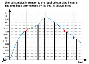
 Interface 'jitter', which results from clock-data degradation, can cause your waveform to be constructed with amplitude errors, seen in the diagram. These could produce noise and distortion. It's for this reason that people sometimes use a dedicated master clock, which all other devices are 'slaved' to.
James Coxon, via email
SOS Technical Editor Hugh Robjohns replies: Digital audio is represented by a series of samples, each one denoting the amplitude of the audio waveform at a specific point in time. The digital clocking signal — known as a 'sample clock' or, more usually, a 'word clock' — defines those points in time.
When digital audio is being transferred between equipment, the receiving device needs to know when each new sample is due to arrive, and it needs to receive a word clock to do that. Most interface formats, such as AES3, S/PDIF and ADAT, carry an embedded word-clock signal within the digital data, and usually that's sufficient to allow the receiving device to 'slave' to the source device and interpret the data correctly.
Unfortunately, that embedded clock data can be degraded by the physical properties of the connecting cable, resulting in 'interface jitter', which leads to instability in the retrieved clocking information. If this jittery clock is used to construct the waveform — as it often is in simple D-A and A-D converters — it will result in amplitude errors that could potentially produce unwanted noise and distortion.
For this reason, the better converters go to great lengths to avoid the effects of interface jitter, using a variety of bespoke re-clocking and jitter-reduction systems. However, when digital audio is passed between two digital devices — from a CD player to a DAW, say — the audio isn't actually reconstructed at all. The devices are just passing and receiving one sample value after another and, provided the numbers themselves are transferred accurately, the timing isn't critical at all. In that all-digital context, interface jitter is totally irrelevant: jitter only matters when audio is being converted to or from the digital and analogue domains.
Where an embedded clock isn't available, or you want to synchronise the sample clocks of several devices together (as you must if you want to be able to mix digital signals from multiple sources), the master device's word clock must be distributed to all the slave devices, and those devices specifically configured to synchronise themselves to that incoming master clock.
An orchestra can only have one conductor if you want everyone to play in time together and, in the same way, a digital system can only have one master clock device. Everything else must slave to that clock. The master device is typically the main A-D converter in most systems, which often means the computer's audio interface, but in large and complex systems it might be a dedicated master clock device instead.
The word clock can be distributed to equipment in a variety of forms, depending on the available connectivity, but the basic format is a simple word-clock signal, which is a square wave running at the sample rate. It is traditionally carried on a 75Ω video cable equipped with BNC connectors. It can also be passed as an embedded clock on an AES3 or S/PDIF cable (often known as 'Digital Black' or the AES11 format), and in audio-video installations a video 'black and burst' signal might be used in some cases.
